Most people grab the first solution that works. Tongue meets slot. Done. Ship it. But "works" and "works reliably at scale" are two very different creatures... and the gap between them is where craft lives.
There's a progression here that mirrors almost everything worth building.
Start simple. Learn the limits. Iterate. Then design something that couldn't exist any other way.
Let's walk through it.
The Obvious First Move
A basic tongue-and-slot joint is where most people start when they need two 3D printed parts to connect. Square peg, square hole. It's easy to design, easy to understand, and... honestly... not great at its actual job.

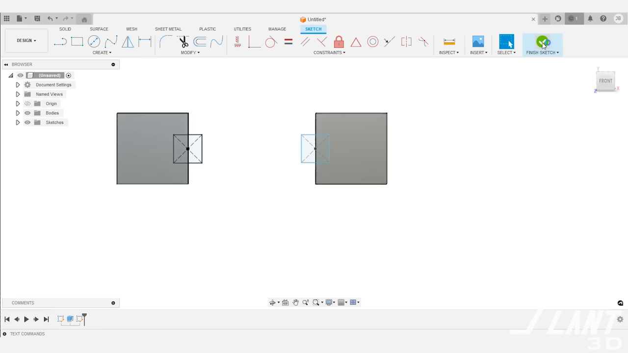
The pieces slide together. They don't really hold together. There's no active pulling force keeping that seam tight. Tolerance issues creep in. Material shrinks differently batch to batch. You end up with parts that jiggle, gap, or just quietly fail when someone handles them.
Chamfering the insert edge helps. The FDM layer lines can grab each other and create a friction lock. But you're still hoping physics cooperates rather than designing certainty into the joint.
Good enough to prototype. Not good enough to produce.
Adding Lateral Support
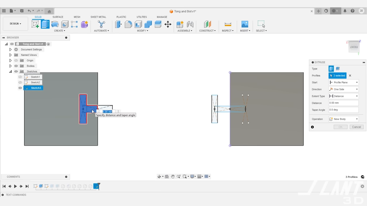
The T-slot joint is the natural next step. You get lateral retention... I can't just pull these apart anymore. That's real progress. But you've also multiplied your tolerance problems. More dimensions to control means more places to fail.
And here's the manufacturing truth that separates hobbyists from production thinkers: that T-shaped cross section creates a complex first layer on the build plate. High-warp materials curl. Parts fail before they're even built. The design works in CAD. It fights you on the printer.
Functionally okay. Manufacturably fragile. Two very different grades.
Where Craft Gets Interesting
This is the moment I love.
Someone looked at that rigid T-slot and asked a better question: What if the flanges weren't rigid?
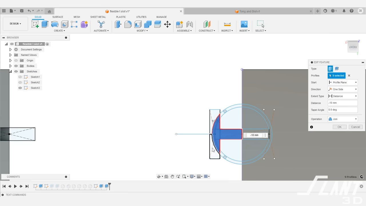
By curving the outer flanges of the T-slot just slightly, they become spring-loaded features. Now instead of forcing a friction fit between two rigid surfaces... you have geometry that actively compensates. Material shrinks a little? The springs still engage. Tolerance drifts? The springs adapt.
No jiggle. No gap. No hoping.
BAM... you've got a joint that pulls itself tight.
And the first layer problem? Solved by angling the slot so the part sits on a simple, flat square base with filleted edges. All the complexity happens later in the print where it's easy to control. The bed adhesion is clean. The part just... works.
That combination of spring T-slot geometry and design for manufacturability is genuinely elegant. Not flashy. Just quietly brilliant.
The I-Slot and Grip Fins
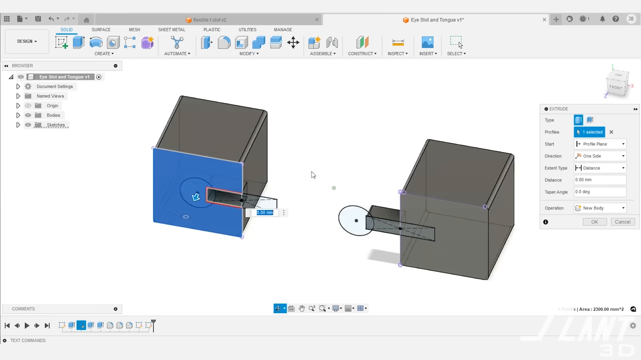
The I-slot joint simplifies the tolerance game even further. One circle centered to another circle. No X-Y dimensional juggling. Chamfer the edges and the layer lines bind the pieces together with decent retention.
But the real gem is the grip fin variant. Small flexible tabs inside the receiving hole that grab the cylindrical tongue from all sides. You can tune the stiffness by changing fin thickness and length. You can create rigid locks or semi-flexible joints that allow minor adjustment while still centering reliably.
These fins use what the presenter rightly calls "impossible geometry"... internal features that can't be machined, can't be molded, can only be 3D printed. The manufacturing method isn't a limitation here. It's the enabler.
The Design That Couldn't Exist Before
And then... the snap-fit locking tab.
Two internal recesses hidden inside a receiving slot. Two small bumps on flexible flanges that click into those recesses when pressed together. The geometry is completely internal... impossible to reach with a cutting tool, impossible to release from an injection mold, impossible to manufacture with anything except additive manufacturing.
This is the kind of design that makes me think about the difference between using a tool and thinking in a tool.
Every previous joint type could be made with traditional methods. CNC. Injection molding. Maybe not as conveniently, but possible. This one? Only exists because someone understood what FDM 3D printing uniquely enables and designed into that capability instead of around it.
The tabs are angled at the bottom so they print without support structures. The first layers are simple. Assembly is fast... press, click, done. You can tune the bumps for permanent locks or reversible connections depending on your use case.
Less material. More reliable. Easier to assemble. Easier to tolerance. And fundamentally impossible to make any other way.
The Deeper Pattern
Here's what actually landed for me watching this progression.
Every upgrade came from the same discipline: identify what's actually failing and solve that specific thing. Not redesign everything from scratch. Not add complexity for its own sake. Just find the weak point, understand the physics, and respond with intention.
Jiggle? Add springs.
First layer warping? Angle the base.
Tolerance stacking? Simplify the geometry.
No pull force? Design a snap lock.
That's not just engineering. That's how you build anything that lasts... relationships, organizations, systems. You don't fix everything at once. You find the real failure point and address it with precision.
The best design isn't the most complex. It's the one where every feature earns its place.
If you're designing multi-part assemblies for 3D printing... especially at scale... study this progression. Start with the spring T-slot if you need something reliable today. Aim for snap-fit locking tabs when you're ready to design for what only this technology can do. And whatever you build, keep asking the question that drives all good craft: What's actually failing here, and what's the simplest geometry that solves it? ✨
Original video by Slant 3D — Watch on YouTube ↗
Design Better Holes | Improve Tolerances | Reduce A comprehensive walkthrough of hole design techniques for FDM 3D printing… from fillets and teardrops through crush riSupport Structures, Slant 3DThese Cooling Vents are Impossible | Design for Ma3D printing transforms passive vent covers into active performance components by enabling internal geometries… S-curveRealm-Work, Craft Mastery
Echoes
Wisdom from across the constellation that resonates with this article.
“Consider thermally conductive filaments for integrated heat exchanger vent designs”
— Slant 3D | These Cooling Vents are Impossible | Design for Mass Production 3D Printing Same Expert
“Test vortex generator tooth patterns in cooling duct designs to improve heat exchange”
— Slant 3D | These Cooling Vents are Impossible | Design for Mass Production 3D Printing Same Expert
“Explore S-curve and serpentine internal geometries for applications requiring light blocking or particulate filtering”
— Slant 3D | These Cooling Vents are Impossible | Design for Mass Production 3D Printing Same Expert